28.05.2017, 02:43 PM
(Dieser Beitrag wurde zuletzt bearbeitet: 28.05.2017, 02:49 PM von christianw..)
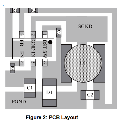
Um nochmal auf meinen Layoutvorschlag zurückzukommen, MP zeigt im DB folgendes:

Und sagt:
Keep the path of switching current short
and minimize the loop area formed by the
input capacitor, high-side MOSFET, and
Schottky diode.
Keep the connection from the power
ground → Schottky diode → SW pin as short
and wide as possible.
Ensure all feedback connections are short
and direct. Place the feedback resistors
and compensation components as close to
the chip as possible.
Connect IN, SW, and especially GND to
large copper areas to cool the chip for
improved thermal performance and long-
term reliability. For single layer PCBs, avoid
soldering the exposed pad.
Das Gegenteil von dem jetzigen Layout.
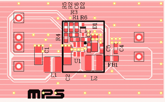
Oder Eval:

Und sagt:
Keep the path of switching current short
and minimize the loop area formed by the
input capacitor, high-side MOSFET, and
Schottky diode.
Keep the connection from the power
ground → Schottky diode → SW pin as short
and wide as possible.
Ensure all feedback connections are short
and direct. Place the feedback resistors
and compensation components as close to
the chip as possible.
Connect IN, SW, and especially GND to
large copper areas to cool the chip for
improved thermal performance and long-
term reliability. For single layer PCBs, avoid
soldering the exposed pad.
Das Gegenteil von dem jetzigen Layout.

Oder Eval:
